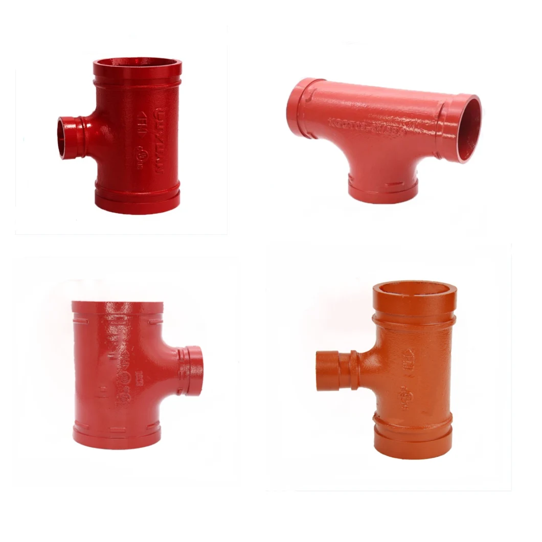
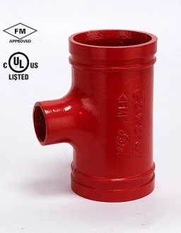
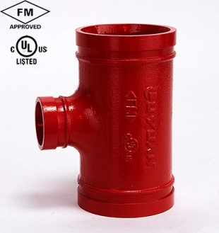
| Item Name | Reducing tee |
| Use | Engineering construction( fire protection,pipe transportation,water pipe, cable protection, mine industry,etc.) |
| Material | Ductile cast iron conforming to ASTM A-536, Grade 65-45-12 |
| Cerification | ISO 9001:2008,FM,UL,CCC and CE approved |
| Technology | Casting |
| Color | Many colors available for choice(Blue,Red,Silver) |
| Surface Treatment | Epoxy powder coating (Red color- RAL3000; Orange)Optional: Galvanized (Zinc Plated, HDG Or Dip painted) |
| Size | 1"-12" |
| Working Pressure | 300PSI |
| Connect End Type | Grooved end ,Thread end |
| Delivery | 15 days |
| Packing Details | Cartons or Cartons on Pallet |
| Payment | By T/T,L/C |
| OEM | YES |
| Factory | YES |
| Brand Name | Plato |
| Type of production | 1) Rigid Coupling,Flexible Coupling, Reducing Flexible Coupling |
| 2) Long Radius and Short Radius Elbow (90°/45°/22.5°/11.25°) | |
| 3) Equal Tee, Grooved Reducing Tee, Grooved Reduing Tee(Threaded outlet) | |
| 4) Grooved Mechanical Tee,Grooved Mechanical Cross | |
| 5) Equal Cross, Grooved Reducing Cross | |
| 6) Grooved Reducer, Threaded Reducer | |
| 7) Adapter Flange, Grooved Split Flange | |
| 8) Cap,End Cap |
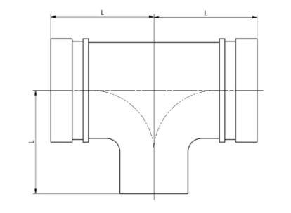
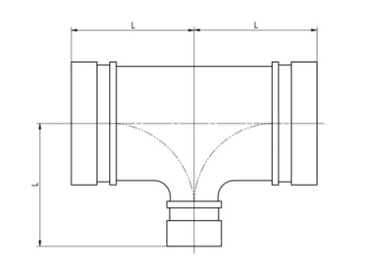
| Nominal Size mm/in | Pipe O.D mm/in | Working Pressure PSI/Mpa | Dimension L mm/in | Nominal Size mm/in | Pipe O.D mm/in | Working Pressure PSI/Mpa | Dimension L mm/in | |
| 50×25 | 60.3×33.7 | 300 | 70 2. 756 | 100×25 | 108.0×33.7 | 300 | 102 4.016 | |
| 2×1 | 2.375×1.315 | 2.07 | 4¼ OD×1 | 4.250×1.315 | 2.07 | |||
| 50×32 | 60.3×42.4 | 300 | 100×32 | 108.0×42.4 | 300 | |||
| 2×1¼ | 2.375×1.660 | 2.07 | 4¼ OD×1¼ | 4.250×1.660 | 2.07 | |||
| 50×40 | 60.3×48.3 | 300 | 100×40 | 108.0×48.3 | 300 | |||
| 2×1½ | 2.375×1.900 | 2.07 | 4¼ OD×1½ | 4.250×1.900 | 2.07 | |||
| 65×25 | 73.0×33.7 | 300 | 76 2.992 | 100×50 | 108.0×60.3 | 300 | ||
| 2½×1 | 2.875×1.315 | 2.07 | 4¼ OD×2 | 4.250×2.375 | 2.07 | |||
| 65×32 | 73.0×42.4 | 300 | 100×65 | 108.0×73.0 | 300 | |||
| 2½×1¼ | 2.875×1.660 | 2.07 | 4¼ OD×2½ | 4.250×2.875 | 2.07 | |||
| 65×40 | 73.0×48.3 | 300 | 100×65 | 108.0×76.1 | 300 | |||
| 2½×1½ | 2.875×1.900 | 2.07 | 4¼ OD×3OD | 4.250×3.000 | 2.07 | |||
| 65×50 | 73.0×60.3 | 300 | 100×80 | 108.0×88.9 | 300 | |||
| 2½×2 | 2.875×2.375 | 2.07 | 4¼ OD×3 | 4.250×3.500 | 2.07 | |||
| 65×25 | 76.1×33.7 | 300 | 100×25 | 114.3×33.7 | 300 | |||
| 3OD×1 | 3.000×1.315 | 2.07 | 4×1 | 4.500×1.315 | 2.07 | |||
| 65×32 | 76.1×42.4 | 300 | 100×32 | 114.3×42.4 | 300 | |||
| 3OD×1¼ | 3.000×1.660 | 2.07 | 4×1¼ | 4.500×1.660 | 2.07 | |||
| 65×40 | 76.1×48.3 | 300 | 100×40 | 114.3×48.3 | 300 | |||
| 3OD×1½ | 3.000×1.900 | 2.07 | 4×1½ | 4.500×1.900 | 2.07 | |||
| 65×50 | 76.1×60.3 | 300 | 100×50 | 114.3×60.3 | 300 | |||
| 3OD×2 | 3.000×2.375 | 2.07 | 4×2 | 4.500×2.375 | 2.07 | |||
| 80×25 | 88.9×33.7 | 300 | 86 3.386 | 100×65 | 114.3×73.0 | 300 | ||
| 3×1 | 3.500×1.315 | 2.07 | 4×2½ | 4.500×2.875 | 2.07 | |||
| 80×32 | 88.9×42.4 | 300 | 100×65 | 114.3×76.1 | 300 | |||
| 3×1¼ | 3.500×1.660 | 2.07 | 4×3OD | 4.500×3.000 | 2.07 | |||
| 80×40 | 88.9×48.3 | 300 | 100×80 | 114.3×88.9 | 300 | |||
| 3×1½ | 3.500×1.900 | 2.07 | 4×3 | 4.500×3.500 | 2.07 | |||
| 80×50 | 88.9×60.3 | 300 | 125×25 | 133.0×33.7 | 300 | 108 4.252 | ||
| 3×2 | 3.500×2.375 | 2.07 | 5¼ OD×1 | 5.250×1.315 | 2.07 | |||
| 80×65 | 88.9×73.0 | 300 | 125×32 | 133.0×42.4 | 300 | |||
| 3×2½ | 3.500×2.875 | 2.07 | 5¼ OD×1¼ | 5.250×1.660 | 2.07 | |||
| 80×65 | 88.9×76.1 | 300 | 125×40 | 133.0×48.3 | 300 | |||
| 3×3OD | 3.500×3.000 | 2.07 | 5¼ OD×1½ | 5.250×1.900 | 2.07 | |||
| Nominal Size mm/in | Pipe O.D mm/in | Working Pressure PSI/Mpa | Dimension L mm/in | Nominal Size mm/in | Pipe O.D mm/in | Working Pressure PSI/Mpa | Dimension L mm/in | |
| 125×50 | 133.0×60.3 | 300 | 108 4.252 | 125×50 | 141.3×60.3 | 300 | 108 4.252 | |
| 5¼ OD×2 | 5.250×2.375 | 2.07 | 5×2 | 5.563×2.375 | 2.07 | |||
| 125×65 | 133.0×73.0 | 300 | 125×65 | 141.3×73.0 | 300 | |||
| 5¼ OD×2½ | 5.250×2.875 | 2.07 | 5×2½ | 5.563×2.875 | 2.07 | |||
| 125×65 | 133.0×76.1 | 300 | 125×65 | 141.3×76.1 | 300 | |||
| 5¼ OD×3OD | 5.250×3.000 | 2.07 | 5×3OD | 5.563×3.000 | 2.07 | |||
| 125×80 | 133.0×88.9 | 300 | 125×80 | 141.3×88.9 | 300 | |||
| 5¼ OD×3 | 5.250×3.500 | 2.07 | 5×3 | 5.563×3.500 | 2.07 | |||
| 125×100 | 133.0×108.0 | 300 | 125×100 | 141.3×108.0 | 300 | |||
| 5¼ OD×4¼ OD | 5.250×4.250 | 2.07 | 5×4¼ OD | 5.563×4.250 | 2.07 | |||
| 125×100 | 133.0×114.3 | 300 | 125×100 | 141.3×114.3 | 300 | |||
| 5¼ OD×4 | 5.250×4.500 | 2.07 | 5×4 | 5.563×4.500 | 2.07 | |||
| 125×25 | 139.7×33.7 | 300 | 125×125 | 141.3×133.0 | 300 | |||
| 5½OD×1 | 5.500×1.315 | 2.07 | 5×5¼ OD | 5.563×5.250 | 2.07 | |||
| 125×32 | 139.7×42.4 | 300 | 150×25 | 159.0×33.7 | 300 | 140 5.512 | ||
| 5½OD×1¼ | 5.500×1.660 | 2.07 | 6¼ OD×1 | 6.250×1.315 | 2.07 | |||
| 125×40 | 139.7×48.3 | 300 | 150×32 | 159.0×42.4 | 300 | |||
| 5½OD×1½ | 5.500×1.900 | 2.07 | 6¼ OD×1¼ | 6.250×1.660 | 2.07 | |||
| 125×50 | 139.7×60.3 | 300 | 150×40 | 159.0×48.3 | 300 | |||
| 5½OD×2 | 5.500×2.375 | 2.07 | 6¼ OD×1½ | 6.250×1.900 | 2.07 | |||
| 125×65 | 139.7×73.0 | 300 | 150×50 | 159.0×60.3 | 300 | |||
| 5½OD×2½ | 5.500×2.875 | 2.07 | 6¼ OD×2 | 6.250×2.375 | 2.07 | |||
| 125×65 | 139.7×76.1 | 300 | 150×65 | 159.0×73.0 | 300 | |||
| 5½OD×3OD | 5.500×3.000 | 2.07 | 6¼ OD×2½ | 6.250×2.875 | 2.07 | |||
| 125×80 | 139.7×88.9 | 300 | 150×65 | 159.0×76.1 | 300 | |||
| 5½OD×3 | 5.500×3.500 | 2.07 | 6¼ OD×3OD | 6.250×3.000 | 2.07 | |||
| 125×100 | 139.7×108.0 | 300 | 150×80 | 159.0×88.9 | 300 | |||
| 5½OD×4¼ OD | 5.500×4.250 | 2.07 | 6¼ OD×3 | 6.250×3.500 | 2.07 | |||
| 125×100 | 139.7×114.3 | 300 | 150×100 | 159.0×108.0 | 300 | |||
| 5½OD×4 | 5.500×4.500 | 2.07 | 6¼ OD×4¼ OD | 6.250×4.250 | 2.07 | |||
| 125×25 | 141.3×33.7 | 300 | 150×100 | 159.0×114.3 | 300 | |||
| 5×1 | 5.563×1.315 | 2.07 | 6¼ OD×4 | 6.250×4.500 | 2.07 | |||
| 125×32 | 141.3×42.4 | 300 | 150×125 | 159.0×133.0 | 300 | |||
| 5×1¼ | 5.563×1.660 | 2.07 | 6¼ OD×5¼ OD | 6.250×5.250 | 2.07 | |||
| 125×40 | 141.3×48.3 | 300 | 150×125 | 159.0×139.7 | 300 | |||
| 5×1½ | 5.563×1.900 | 2.07 | 6¼ OD×5½OD | 6.250×5.500 | 2.07 | |||
| Nominal Size mm/in | Pipe O.D mm/in | Working Pressure PSI/Mpa | Dimension L mm/in | Nominal Size mm/in | Pipe O.D mm/in | Working Pressure PSI/Mpa | Dimension L mm/in | |
| 150×125 | 159.0×141.3 | 300 | 140 5.512 | 150×65 | 168.3×76.1 | 300 | 140 5.512 | |
| 6¼ OD×5 | 6.250×5.563 | 2.07 | 6×3OD | 6.625×3.000 | 2.07 | |||
| 150×25 | 165.1×33.7 | 300 | 150×80 | 168.3×88.9 | 300 | |||
| 6½ OD×1 | 6.500×1.315 | 2.07 | 6×3 | 6.625×3.500 | 2.07 | |||
| 150×32 | 165.1×42.4 | 300 | 150×100 | 168.3×108.0 | 300 | |||
| 6½ OD×1¼ | 6.500×1.660 | 2.07 | 6×4¼ OD | 6.625×4.250 | 2.07 | |||
| 150×40 | 165.1×48.3 | 300 | 150×100 | 168.3×114.3 | 300 | |||
| 6½ OD×1½ | 6.500×1.900 | 2.07 | 6×4 | 6.625×4.500 | 2.07 | |||
| 150×50 | 165.1×60.3 | 300 | 150×125 | 168.3×133.0 | 300 | |||
| 6½ OD×2 | 6.500×2.375 | 2.07 | 6×5¼ OD | 6.625×5.250 | 2.07 | |||
| 150×65 | 165.1×73.0 | 300 | 150×125 | 168.3×139.7 | 300 | |||
| 6½ OD×2½ | 6.500×2.875 | 2.07 | 6×5½OD | 6.625×5.500 | 2.07 | |||
| 150×65 | 165.1×76.1 | 300 | 150×125 | 168.3×141.3 | 300 | |||
| 6½ OD×3OD | 6.500×3.000 | 2.07 | 6×5 | 6.625×5.563 | 2.07 | |||
| 150×80 | 165.1×88.9 | 300 | 200×25 | 219.1×33.7 | 300 | |||
| 6½ OD×3 | 6.500×3.500 | 2.07 | 8×1 | 8.625×1.315 | 2.07 | |||
| 150×100 | 165.1×108.0 | 300 | 200×32 | 219.1×42.4 | 300 | |||
| 6½ OD×4¼ OD | 6.500×4.250 | 2.07 | 8×1¼ | 8.625×1.660 | 2.07 | |||
| 150×100 | 165.1×114.3 | 300 | 200×40 | 219.1×48.3 | 300 | |||
| 6½ OD×4 | 6.500×4.500 | 2.07 | 8×1½ | 8.625×1.900 | 2.07 | |||
| 150×125 | 165.1×133.0 | 300 | 200×50 | 219.1×60.3 | 300 | |||
| 6½ OD×5¼ OD | 6.500×5.250 | 2.07 | 8×2 | 8.625×2.375 | 2.07 | |||
| 150×125 | 165.1×139.7 | 300 | 200×65 | 219.1×73.0 | 300 | |||
| 6½ OD×5½OD | 6.500×5.500 | 2.07 | 8×2½ | 8.625×2.875 | 2.07 | |||
| 150×125 | 165.1×141.3 | 300 | 200×65 | 219.1×76.1 | 300 | |||
| 6½ OD×5 | 6.500×5.563 | 2.07 | 8×3OD | 8.625×3.000 | 2.07 | |||
| 150×25 | 168.3×33.7 | 300 | 200×80 | 219.1×88.9 | 300 | |||
| 6×1 | 6.625×1.315 | 2.07 | 8×3 | 8.625×3.500 | 2.07 | |||
| 150×32 | 168.3×42.4 | 300 | 200×100 | 219.1×108.0 | 300 | |||
| 6×1¼ | 6.625×1.660 | 2.07 | 8×4¼ OD | 8.625×4.250 | 2.07 | |||
| 150×40 | 168.3×48.3 | 300 | 200×100 | 219.1×114.3 | 300 | |||
| 6×1½ | 6.625×1.900 | 2.07 | 8×4 | 8.625×4.500 | 2.07 | |||
| 150×50 | 168.3×60.3 | 300 | 200×125 | 219.1×133.0 | 300 | |||
| 6×2 | 6.625×2.375 | 2.07 | 8×5¼ OD | 8.625×5.250 | 2.07 | |||
| 150×65 | 168.3×73.0 | 300 | 200×125 | 219.1×139.7 | 300 | |||
| 6×2½ | 6.625×2.875 | 2.07 | 8×5½OD | 8.625×5.500 | 2.07 | |||
| Nominal Size mm/in | Pipe O.D mm/in | Working Pressure PSI/Mpa | Dimension L mm/in | Nominal Size mm/in | Pipe O.D mm/in | Working Pressure PSI/Mpa | Dimension L mm/in | |
| 200×125 | 219.1×141.3 | 300 | 250×150 | 273.0×168.3 | 300 | |||
| 8×5 | 8.625×5.563 | 2.07 | 10×6 | 10.750×6.625 | 2.07 | |||
| 200×150 | 219.1×159.0 | 300 | 250×200 | 273.0×219.1 | 300 | |||
| 8×6 | 8.625×6.250 | 2.07 | 10×8 | 10.750×8.625 | 2.07 | |||
| 200×150 | 219.1×165.1 | 300 | 300×25 | 323.9×33.7 | 300 | |||
| 8×6½ OD | 8.625×6.500 | 2.07 | 12×1 | 12.750×1.315 | 2.07 | |||
| 200×150 | 219.1×168.3 | 300 | 300×32 | 323.9×42.4 | 300 | |||
| 8×6 | 8.625×6.625 | 2.07 | 12×1¼ | 12.750×1.660 | 2.07 | |||
| 250×25 | 273.0×33.7 | 300 | 300×40 | 323.9×48.3 | 300 | |||
| 10×1 | 10.750×1.315 | 2.07 | 12×1½ | 12.750×1.900 | 2.07 | |||
| 250×32 | 273.0×42.4 | 300 | 300×50 | 323.9×60.3 | 300 | |||
| 10×1¼ | 10.750×1.660 | 2.07 | 12×2 | 12.750×2.375 | 2.07 | |||
| 250×40 | 273.0×48.3 | 300 | 300×65 | 323.9×73.0 | 300 | |||
| 10×1½ | 10.750×1.900 | 2.07 | 12×2½ | 12.750×2.875 | 2.07 | |||
| 250×50 | 273.0×60.3 | 300 | 300×65 | 323.9×76.1 | 300 | |||
| 10×2 | 10.750×2.375 | 2.07 | 12×3OD | 12.750×3.000 | 2.07 | |||
| 250×65 | 273.0×73.0 | 300 | 300×80 | 323.9×88.9 | 300 | |||
| 10×2½ | 10.750×2.875 | 2.07 | 12×3 | 12.750×3..500 | 2.07 | |||
| 250×65 | 273.0×76.1 | 300 | 300×100 | 323.9×108.0 | 300 | |||
| 10×3OD | 10.750×3.000 | 2.07 | 12×4¼ OD | 12.750×4.250 | 2.07 | |||
| 250×80 | 273.0×88.9 | 300 | 300×100 | 323.9×114.3 | 300 | |||
| 10×3 | 10.750×3.500 | 2.07 | 12×4 | 12.750×4.500 | 2.07 | |||
| 250×100 | 273.0×108.0 | 300 | 300×125 | 323.9×133.0 | 300 | |||
| 10×4¼ OD | 10.750×4.250 | 2.07 | 12×5¼ OD | 12.750×5.250 | 2.07 | |||
| 250×100 | 273.0×114.3 | 300 | 300×125 | 323.9×139.7 | 300 | |||
| 10×4 | 10.750×4.500 | 2.07 | 12×5½OD | 12.750×5.500 | 2.07 | |||
| 250×125 | 273.0×133.0 | 300 | 300×125 | 323.9×141.3 | 300 | |||
| 10×5¼ OD | 10.750×5.250 | 2.07 | 12×5 | 12.750×5.563 | 2.07 | |||
| 250×125 | 273.0×139.7 | 300 | 300×125 | 323.9×159.0 | 300 | |||
| 10×5½OD | 10.750×5.500 | 2.07 | 12×6¼ OD | 12.750×6.250 | 2.07 | |||
| 250×125 | 273.0×141.3 | 300 | 300×125 | 323.9×165.1 | 300 | |||
| 10×5 | 10.750×5.563 | 2.07 | 12×6½ OD | 12.750×6.500 | 2.07 | |||
| 250×150 | 273.0×159.0 | 300 | 300×125 | 323.9×168.3 | 300 | |||
| 10×6¼ OD | 10.750×6.250 | 2.07 | 12×6 | 12.750×6.625 | 2.07 | |||
| 250×150 | 273.0×165.1 | 300 | 300×150 | 323.9×219.1 | 300 | |||
| 10×6½ OD | 10.750×6.500 | 2.07 | 12×8 | 12.750×8.625 | 2.07 | |||
According to the design specification of automatic sprinkler system, the pipe connection of the system should be made with trench connector or thread and flange.Pipes with diameter equal to or greater than 100mm in the system shall be connected with flanged or grooved connectors in sections. Groove pipe fitting connection technology, also known as clamp connection technology, has become the first technology for liquid and gas pipe connection. Although this technology was developed later in China than abroad, it was quickly accepted by the domestic market due to its advanced technology.Since 1998, it has been developed, and after a few years of development and application, it has gradually replaced the two traditional pipe connection methods of flange and welding.Not only is the technology more mature, the market is generally recognized, and has been actively guided by national laws and policies. The application of groove fitting connection technology makes the complicated pipeline connection process simple, quick and convenient.This is a big step forward in pipeline connection technology.
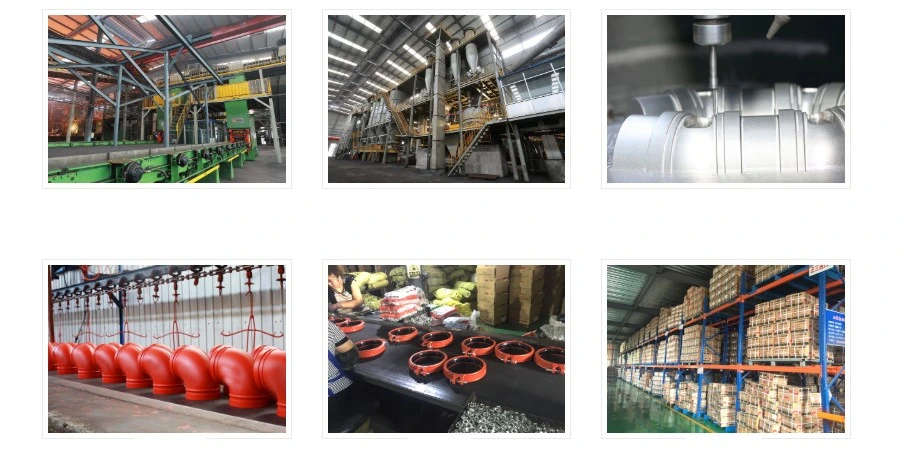
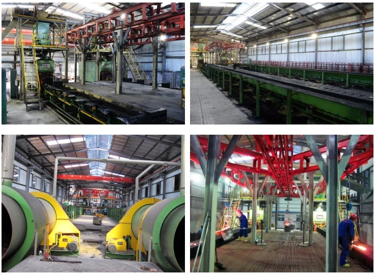
Production Flow
Melting-----Sand Mixing-----Casting-----Shot Blasting&Polishing-----Pressure Testing-----Powder Paiting------Drying&Curing----Assembling-----Packing
Quality Test
Material Testing-----Gasket Test, Sand Test.
Semi-Finished Products-----Leak Test, Tensile Strength Test, Salt Spray Test, Dimention Inspection, Working Pressure Test.
Finished Products-----Final Visual Inspection.
Groove pipe fittings include two major categories of products:
(1) the connection sealing effect of the pipe fitting has a rigid joint, flexible joint, mechanical tee and groove flange;
(2) to connect the transition role of the pipe elbow, tee, tee, reducing pipe, blind plate, etc.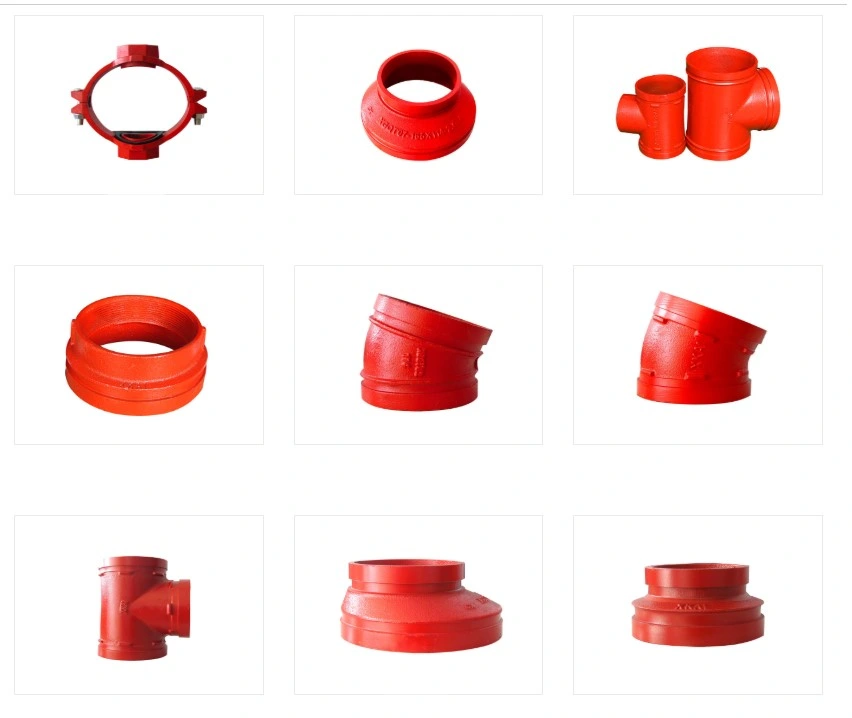
As an advanced way of pipe connection, trench fitting connection can be either explicitly or embedded, with both rigid and flexible joints.Therefore, it has a wide range of application.
(1) according to the system: can be used for fire water system, air conditioning hot and cold water system, water supply system, petrochemical pipeline system, thermal and military pipeline system, sewage treatment pipeline system;
(2) according to the pipe material: can be used to connect steel pipe, copper pipe, stainless steel pipe, lined steel pipe, ductile iron pipe, thick wall plastic pipe and with steel pipe joint and flange joint hose and valves.
Nine big advantages
1, quickly take the groove clamp contact and the corresponding pipe fitting placement pipeline, start construction do not need to be welded, do not need to be twice galvanized, twice placement.Increased placement rate.
2, light weight of contact clamp, bolt number is small, easy placement, do not need extra skills.
3, reliable scientific and fair mechanism design, peculiar c-type rubber seal ring, triple seal, guarantee the reliability of the connection seal.
4, peace with the trench clamp contact and the corresponding pipe fittings placement start, only mechanical assembly, no welding, no open fire, therefore, there is no welding slag muddy pipeline, can ensure the site safety, for the fire conditions of the construction, especially suitable.
5, the economy because the placement is fast, do not need extra skills, placement repair rate is low, so the comprehensive placement cost than flange can save 30-50%.
6, take up space small groove type clamp contact connection space is about 70% of the flange, and due to the number of fastening bolts and no object, especially practical space under narrow conditions of construction.
7, the maintenance of a brief safe and reliable product size, as long as the proper placement, pipeline is a test pressure pass, safe operation, usually no maintenance, spare parts for decades without replacement.
8 ,Universal groove clamp connection can be used to connect seamless steel tubes, galvanized steel tubes, welded steel tubes, stainless steel tubes, copper tubes and other metal tubes.
9, The connected pipeline is a flexible system, which can absorb the length displacement of the pipe due to temperature change and allow the pipe to have a certain deviation Angle.
Our products were sold to Middle east,South Africa,North America and Europe markets,we can also accept customized products,and we 'll try our best to provide the best service and products for you .

FAQ
Q: Are you trading company or manufacturer ?
A: We are a factory with a trading department.
Q: How long is your delivery time?
A: Generally 15 days after the down payment. OEM 30 to 90 days.
Q: Do you provide samples ? is it free or extra ?
A: Yes, we could offer the sample for free charge but do not pay the cost of freight.
Q: What is your terms of payment ?
A: Payment<=1000USD, 100% in advance.
Payment>=1000USD, 30% T/T in advance ,balance before shippment.
If you have another question, pls feel free to contact us.
Welcome to our factory to have a visit.